Elektrische Schlafaugen Cougar 1969 & 1970
|
Electric Headlight Covers for 1969/70 Cougars |
By Bruce Habel
|
Hidden headlights, like sequential turn signals, are part of what makes the early Cougars stand out from the crowd. When these systems work poorly--or do not work at all--not only is the effect ruined but the car can be hazardous to operate. The vacuum operated headlight doors can be a particular pain to maintain. Low vacuum and leaks from the 30+ year old parts conspire to bring the system down. The low availability and high cost of replacement parts does not help the situation. For those reasons and some aesthetic ones as well, I decided to convert the vacuum system over to electric. My requirements for the new system were simple. One, it had to bolt in without modifying any original parts. Two, it must be made from readily available materials. Three, it must not significantly increase the power load. This system does all those things, although one optional refinement does put two additional holes in one arm. Because the tolerances in our new system are much tighter than before, it may require the repair or replacement of the two headlight door arms if their rag joints are worn. The hardest part of the conversion is the fabrication of the lever arm and motor arm. Obviously, there are some electrical modifications, but no wires are cut or spliced. This system allows the headlight doors to even work in heavily modified cars with motors that don't produce sufficient vacuum to operate the doors, it also cleans up the engine compartment by removing the vacuum hoses. It will add from one to three wires beside the original wiring harness, how many depends upon the wiring system chosen. From a money standpoint, it is probably cheaper to repair the original system. For what it costs to build this system you can buy a new vacuum motor, all new hoses and a maybe even a new headlight switch. Its strong points are the cleaner engine compartment via the removal of the three vacuum hoses, elimination of associated vacuum leaks, and being able to shut the headlight doors after the car is turned off. The doors will also open and close a little quicker than before. The system described here is for 1969-70 Cougars. The brackets will not work in the 67-68 Cougars as they used a different setup. My design for 1967-68 Cougars is located in Restomods & Upgrades area of TCCN II's Tech How-To Section. The new bracket uses three attachment points instead of the two used by be the original vacuum motor, as the vacuum motor only pulled or pushed in a straight line. The electric motor produces stress in directions the original brackets were not designed to handle. For this reason the electric motor bracket has a "U" shaped section at it is top to connect the vacuum motor brackets together like the original motor and also bolts directly to the frame of the car. The "U" section reinforces the middle section of the brackets and keeps them from twisting, while bolting it to the frame gives it a solid anchor point. This project has a lot of steps, but they can be broken down into five stages. First is buying the materials, followed by inspecting and evaluating some of the original parts being reused. Next comes making and installing the new parts. After that is wiring with the last stage being testing and final adjustments. This article includes twelve diagrams on separate web pages, and accessed by the links in the chart below and by links in the article text. Many of these diagrams can be used as templates for cutting parts if your printer prints them accurately--check the measurements on the diagrams with a ruler to be sure the scale is correct. You can save or print any of the diagrams by right-clicking on the diagram image and selecting your preference from the pop-up menu. |
| Motor Mount Starting Cuts | |
| DIAGRAM 2 | Motor Bracket U Section |
| DIAGRAM 3 | Motor Bracket Center Section Cut Sheet |
| DIAGRAM 4 | Motor Bracket Center Section |
| DIAGRAM 5 | Motor Bracket Connections |
| DIAGRAM 6 | Motor Bracket Lower Section |
| DIAGRAM 7 | Spring Support |
| DIAGRAM 8 | Lever Arms |
| DIAGRAM 9 | Motor Arms |
| DIAGRAM 10 | Wiring: Relay in Passenger Compartment |
| DIAGRAM 11 | Wiring: Relay in Engine Bay/Power From Fuse Panel |
| DIAGRAM 12 | Wiring: Relay in Engine Bay/Power From Battery |
|
Not counting buying the parts, the estimated time to complete the project is thirty hours for a person familiar with the recommended tools. Set aside two weekends and let's get started! STAGE 1: SUPPLIES AND EQUIPMENT TOOLS |
| MIG welder | 7/16" wrench & 7/16" socket | ||
| welding helmet | 3/8" wrench & 3/8"socket | ||
| hearing protection | two 3/4" wrenches | ||
| safety goggles | 10mm & 14mm sockets | ||
| angle grinder | ratchet | ||
| grinding discs | 6" extension | ||
| cutting discs | soldering iron | ||
| electrical drill | solder | ||
| drill bits: 9/64" 3/16" 1/4" 5/16" 7/16" | shrink wrap tubing | ||
| flat and round files | lighter/heat gun/hair dryer | ||
| hack saw | liquid electrical tape | ||
| circular sanding discs (80 grit) | dielectric grease | ||
| 5" circular sanding pad for drill | wire cutters | ||
| vice | sandpaper: 320-400 grit & 80-120 grit | ||
| vice grips | primer | ||
| pliers | paint (semi flat black) | ||
| clamps | small flat blade screwdriver | ||
| awl or scribe | rubber sealant | ||
| hammer | silicone lubricant | ||
| 1/2" wrench or socket | corner brace |
|
You might need a propane torch, a framing square and PlastiDip/black rubber gasket sealant. Additionally, a reamer/die grinder/Dremel tool with a cone shaped burr may be useful, depending upon the style of the arms chosen and the amount of time you want to save versus doing the work by hand. PARTS |
| 1 | 89-92 Ford Probe headlight door motor (passenger side) | boneyard | |
| 2 | 3/8" x 1" threaded brass sleeves | hardware store | |
| 4 | 1/2" brass compression nuts | hardware store | |
| 4 | 1/2" washers | hardware store | |
| 2 | cotter pins or 1/4" E-clips | hardware store | |
| 2 | 1/2" fine thread bolts | hardware store | |
| 2 | 1/2" fine thread nuts | hardware store | |
| 1 | 1/2" coarse thread bolt | hardware store | |
| 4-6 | 5/16" flat washers | hardware store | |
| 3 | 1/4" x 2 1/4" bolts | hardware store | |
| 3 | 1/4" lock washers | hardware store | |
| 3 | 1/4" nuts | hardware store | |
| 6 | 1/4" flat washers | hardware store | |
| 2 | #10-24 torx head screws or 3/16" carriage head bolts | hardware store | |
| 2 | 3/16" nuts | hardware store | |
| 1 | 3' of 3/16" steel rod (1' needed) | hardware store | |
| 1 | 3' 5/16" steel rod (1' needed) | hardware store | |
| 2 | 14 gage corner bracing (6" needed) | hardware store | |
| 1 | 3' x 3" x 1/8 flat steel (2' needed) | hardware store | |
| 1 | 3' x ¾" x 3/16" flat steel (1' needed for lever arm option 1 | hardware store | |
| 1 | 1" body plug | auto parts store | |
| 4 | vacuum caps | auto parts store | |
| wire | 18-gage min. length/amount vary (about 80' needed) | auto parts store | |
| 1 | 5-post dimmer relay for 89-92 Ford Probe AAP part #PA5972817 | Advance Auto Parts | |
| 1 | relay connector with all five terminals | boneyard | |
| 1 | inline fuse holder | Radio Shack | |
| 1 | 20A fuse | Radio Shack | |
| 1 | fuse tap | Radio Shack | |
| 2 | ring type wiring terminal for ground wires | Radio Shack | |
| 1 | blade type wiring terminal, male for wiring adapter clip | Radio Shack | |
| 2 | blade type wiring terminal, female for wiring adapter clip and fuse tap. One must have retaining tab to hold terminal in connector. | Pep Boys |
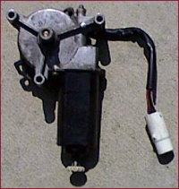 |
The Ford Probe headlight door motor is less expensive from a junkyard and you can get both sides of the electrical connector. That way you do not have to splice into the wiring harness again to replace the motor should it ever go bad. Buy the relay before you go to the yard so you can ensure the connector fits before you buy it. It must fit and have wires in all the slots as all five connectors are used on the relay. Cut the wires about two-three inches away from each connector, to leave room for soldering wires together. Also test the motor at the yard. To test the motor, connect the black wire to ground and the black wire with a white stripe to power. Touch one of the remaining wires to power. |
| The motor arm will rotate 180 degrees then either stop, or do nothing.If it does nothing, disconnect that wire and connect the other wire. The motor should then rotate 180 degrees and stop. Now disconnect that wire and connect the other wire. The motor arm should rotate 180 degrees back to the original position. Once the motor rotates, disconnecting and reconnecting the same wire should have no effect on the motor. Connecting both of the remaining wires to power at the same time will make the motor rotate continuously. If the motor does not turn as described, look for another one. Finally, touch the black wire with the red stripe to power. This will rotate the motor to the down position, which is where the motor needs to be when installed. Note that the wire colors are the ones after the connector since the wire colors change at the connector. If you could not get both sides of the connector, black is still ground, white with a red stripe is constant power, and the red and yellow are the remaining two wires. |
|
STAGE 2: DISCONNECTING THE OLD SYSTEM
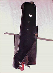
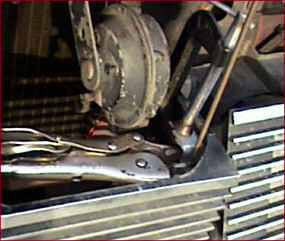
After you acquire the materials, inspect the outer halves of the grill. They must be level and properly aligned. Next remove the center section of the grill. While not required, it will make working on the brackets easier and lessens the chance of the center section getting damaged. Remove the front license plate holder, then disconnect the vacuum lines going to the vacuum motor. The headlight doors will open when the hoses are removed. Remove the two pins and the vacuum motor arm retaining clip in the center bar. Slide the center bar toward the passenger side until it clears the driver’s side light door arm. While making sure it does not reconnect or snag on the driver’s side arm, push the center bar to the driver’s side until it clears the passenger side door arm. The center arm will now clear the hole in the passenger side vacuum motor bracket and can be removed. The bar is longer on one side than the other so it can only be removed one way. Start on the opposite side for 1970 Cats. Using vice grips or pliers, remove the end of the headlight door springs from the spring holders on both sides. Rotate each spring about 3/4" of a turn until the pressure is relieved, then release the spring. Put the headlight door in the closed position if it did not rotate there when removing the spring. Remove the two 1/2" vacuum motor nuts. Let the vacuum motor rest on the front valence for now, as one of the vacuum motor brackets must be removed to get the vacuum motor out. Remove the three 7/16" bolts and three 1/2" bolts holding on to the passenger side vacuum motor bracket, then remove the bracket and the vacuum motor. The bracket will be used as a template in a few steps so leave it out for now. |
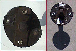 |
Examine the rag joints on the arms that connect to the headlight doors. The rag joints must be round, not egg shaped, and the rivet holes cannot be stretched. Remove the 1/2" nut inside the headlight door holding on the arm and slide the arm out. Note the position of the spring. Put a pair of pliers on each metal piece of the arm and twist in opposite directions. If the metal pieces move at all in relation to each other before the coupler starts to flex, the rivet holes are stretched. |
|
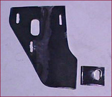
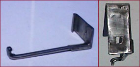
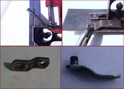
If any rivet holes are stretched or the rag joint is significantly out of round, both arms should be replaced with a matched set. The image on the far left (above) shows a warped rag joint, the right a repaired unit. It is possible to fix these arms using four 5/8" long #10-24 machine screws Use a 5/32" drill bit to drill the new holes. I do not know how long these repairs will last and the rag joint is just about worn out at this point anyway. Once you have a good set of arms, put the springs back on the bars in the same position as before and reinstall the arms. Owners of ’70 models need to put the arms and springs back in so the springs pull the doors open instead of closed. I’ve forgotten which way the ’70 springs pull, but the system needs the springs to pull the doors open, not closed. Disconnect the vacuum line above the driver’s side headlight door going to the vacuum reservoir. Open the clips along the driver’s side fender apron and remove the three vacuum hoses. Leave the clips open for now. Disconnect the vacuum hose at the manifold and install a vacuum cap. Go inside the car and disconnect the three hoses going to the headlight switch. Install vacuum caps on the switch so dirt cannot get inside the switch. Push the connector out of the firewall, then remove the vacuum hoses. Turn the front wheels to the right to gain access to the vacuum reservoir under the left fender. Remove the four 3/8" screws holding the tank to the brackets, and then remove the four 3/8" screws holding the brackets to the fender. Box up the vacuum motor, hoses, and reservoir until such time when they are required again. |
|
STAGE 3: FABRICATION AND INSTALLATION
The electric motor bracket is made in three steps. Start by making the "U" shaped section. Cut the two pieces labeled "A" and "B" out of 3’ x 3" x 1/8" stock as indicated in Diagram 1. Cut 1/2" off one of the 3" pieces, then weld them together to form the "U". Diagram 2 shows the detail for the "U" section. Drill a 5/16" hole on each side of the "U" 2-1/2" down (or 1/2" down for '70s and some '69s (see production variations below for more details) from the open end and centered in each leg. Center a 1/2" nut over each hole on the side where the welding seam was ground smooth and put a bolt through them to hold them in place. Both nuts must be on the same side of the "U". I used fine threaded nuts and bolts, but coarse threaded ones will also work. Use some washers or extra nuts so that the bolt threads do not protrude beyond the nut while welding or welding splatter may damage the bolt threads. Weld the nuts in place, then remove the bolts. Put this section to the side for now. |
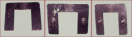 |
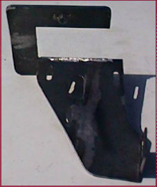
The motor bracket in three steps: Left, the welded unit. Center, initial drilling. Right, the finished piece. |
|
PRODUCTION VARIATIONS The direction of the vacuum motor supports on the brackets changed late in the ‘69 production year. The only thing this affects in our project is the mounting point for the top of the bracket. The 1/2" measurement for these cars was derived the following way. The "U" section mounts 7/8" away from the rear of the vertical edge of the vacuum motor bracket. The distance from the rear of the vertical edge of the vacuum motor bracket to the center of the original ‘70 bolt hole is 1 3/8". Subtracting 7/8" from 1 3/8" produces the 1/2" mounting point. I checked a ’70 for this 1-3/8" measurement, but check it again before drilling. MOTOR BRACKET: CENTER SECTION Next comes the center section. Weld two 7-1/2" sections of the 3" x 1/8" stock together to make the base plate. Start by making the three small slotted holes. The diagrams are made to scale so the simplest way to make the center section is to print out Diagram 3 and use it as a template. (Check the diagram measurements with a ruler to be sure your printer printed them to scale.) Otherwise, scribe the lines using the measurements at the top and bottom of the diagram. The awl makes for a good scribe and the scratches it leaves will not be erased like pen and/or pencil marks that tend to be removed just by handling the piece. Diagram 4 shows the layout of the center section. Find the top of each slot by measuring down the scribed line. Drill four 1/4" holes along the length of the slotted hole. Make sure you take into account the width of the drill bit or the slots will be longer than necessary. In the inner holes, gently wobble the bit from side to side to elongate the holes to connect them to the adjacent holes. Drill bits aren’t designed to do this so take your time and do not apply a lot of pressure or the bit will break. Wear safety glasses just in case the bit breaks despite the care you were taking. Use a file to smooth out the sides of the holes once they are connected. When one of the 1/4" x 2-1/4" bolts will smoothly slide the length of the slot it is finished. Repeat this process for the other two small slots. |
 |
For the large slot, drill lots of little (9/64" or smaller) holes around the perimeter of the large slot, knock the center out, then file the edges smooth. Put the motor shaft in the hole from the backside of the plate and put bolts through the slots into the holes in the motor housing. The motor must slide the length of the slots without binding, filing any offending slot edges until it can. Once the holes are cut scribe the remaining lines onto the section, then cut the material off with the cutting wheel or hack saw. An angle grinder or drill with a cutting wheel can save a lot of time versus a jigsaw or hacksaw. While the paper template is the easiest way, it may not be available. The cut on the rear (right side) is particularly hard to duplicate without a template unless you know a secret, which is the rear curve is an exact duplicate of the curve on the rear of the original motor bracket. |
| Make the top and front cuts first, lay the original vacuum motor bracket on it is side with the vacuum motor support pointing up, then place the section on top of the original vacuum motor bracket, with the rear edge flush against the bracket and the top flush against the underside of the motor support. Scribe the outline of the rear curve onto the center section. Cut along the scribed line. The corners can be rounded if you like, with the exception of the upper left and lower right corners which must be square. This finishes the center section of the bracket. |
 |
Now cut out a 1-1/2" x 1-3/4" rectangle from the material cut from the lower left side of the center section material. Diagram 6 illustrates this lower section of the motor bracket. Make a 7/16" slot in the rectangle like you did before with the 9/64" bit or use a 7/16" bit and file away the middle. The slot must to be 1/4" from the top (1-3/4") and 5/16" from the right side (1-1/2"). This completes all the sections of the motor bracket. Hold the "U" section with the legs facing the rear of the car and the welded bolts facing downward. Slide the center section into the U until it is 1/8" away from the inside edge. |
|
This will put the front edge of the center section 1-5/8" away from the very bottom of the "U". Clamp the sections together with C-clamps or vice grips. A corner brace or section of angle iron comes in handy to keep the edges at 90 degrees to each other. Put the center section 1/16" below the top of the "U" section. Tack weld the two sections together. Recheck to ensure they are still perpendicular to each other, then finish welding the top seam. Fill in the 1/16" difference completely. This difference is there to ensure that sufficient material remains after the weld is ground smooth to keep the seam from cracking. Remove the clamps and weld the seam from the rear. A full seam weld is not necessary, two or three spot weld are sufficient when combined with the front weld. There’s nothing wrong with a full seam weld if you so choose either. To be honest I’m not sure the rear seam even needs to be welded at all if the front weld is done properly, but it does not hurt to be sure. Smooth out the top weld with the grinder, followed by the sanding discs on the drill. Remove any welding splatter from the rear side. Take the lower section and clamp it 1/4" above the bottom edge of the center section with the same 1/16" gap. |
 |
Make sure the hole is closer to the top or you will have to file the opening bigger like I had to when I welded it on upside down. The bottom section should be 1/16 beyond the trailing edge of the center section. The lower section should be beside and slightly beyond the center section, not behind it. Weld the two together, again filling in the gap. A spot weld on the front really is not necessary if the rear weld is sound. No welds on the front also make for a smoother appearance. |
|
The last items to fix on the bracket are the bracket bolts. If they are too long they will hit the motor and prevent proper adjustment. Take two 5/16" washers and put them on a bolt. Screw the bolt into the nut from the top, and then cut the bolt off one or two threads beyond where the bolt protrudes from the nut. Repeat for the other bolt. Remove any welding splatter or residue, then sand, prime and paint the new bracket. A semi-flat black is close to the original color of the vacuum motor brackets. |
| SPRING SUPPORTS The next items are the spring supports. The original headlight design has the springs pulling the doors open if the vacuum fails. The gearing in the electric motor will not allow this to happen and the original spring setup will cause uneven loads on the motor. The doors need to have a neutral balance or the motor will quickly burn out. The new spring supports change the location where the ends of the springs are connected. The new location has the doors held approximately halfway open. The motor has to overcome gravity for half of each cycle and the spring for the other half, but the load is roughly the same between the opening and closing cycles. The driver’s side spring support and passenger side spring support are mirror images of each other. The procedure to make each is the same. Diagram 7 illustrates the spring support design. |
 |
Make the driver’s side first. 1) Start by cutting a 2-1/4" long section of the 14 gage corner steel. Hold the piece so that it looks like an "L." 2) Rotate the piece 180 degrees. Cut 1-3/4" of metal off the back of the vertical edge. This will leave 1/2" of material pointing downward at the right front of the piece. Put the piece over the original spring support and mark the trailing edge. |
|
3) Remove the piece, clamp the 1-3/4" section that was cut off earlier along the line, then fold the trailing edge down and over the 1-3/4" piece. 4) Remove the clamps and the 1-3/4" section, then put the 2-1/4" piece back over the original support. Use pliers or vice grips to ensure the lip is snug against the original support. Draw the outline of the front slot on the underside of the 2-1/4" piece. Cut a 7/8" x 7/16" section out of the 1-3/4" piece. This becomes a spacer so the retaining nut will mount flush. Next take the 3/16" steel rod and put a 90 degree bend in it about ½" from the end. Hold the rod so the 1/2" section is facing you and the rest is pointing upward. Put the rod about 1/2" deep in the vice, then bend the rod to the left. Clamp the rod to a 1" piece of corner steel so that the bottom of the rod is about 3-7/8" from the top of the piece. Clamp the 1" piece to the original spring support. Place the end of the spring on the bottom of the rod. |
 |
Adjust the rod upward or downward until it holds the door halfway open. Unclamp the 1" piece from the car and note the total distance from the bottom of the rod to the top of the 1" piece. While the overall distance from the top of the support to the bottom of the rod should be 3-7/8", weak springs and different door weights can affect the final length. 1970 owners in particular should not blindly accept the 3-7/8" distance as their doors are not the same weight as 1969 doors. Note that the 3 7/8" length includes 1/8" of 14-gage metal so the total length of the rod is actually only 3-3/4". |
| Cut the rod to length, then weld the 7/8" x 7/16" spacer and the rod to the 2-1/4" piece so the 3-7/8" rod is against the front edge of the downward pointing 1/2" section of the support and the spacer is between the rod and the support. Once the rod is welded in place the rod can be tilted forward slightly so the end of the spring is securely held by the bend in the rod, but is not required. The very end of the rod should be pointing forward. Round off the bottom end of the rod. Now drill a hole in the middle of the outline of the slot drawn on the underside. The center of the hole should be 3/8" from the edge closest to the center of the car, but it can vary due to fit and design variations on the original spring support. Use the #10-24 Torx head bolts to install the spring supports. A 3/16" carriage bolt makes for an authentic looking piece but finding 3/16" carriage bolts can be difficult. A regular screw or a small hex head bolt will also work. If you find the carriage bolts, use a small file or a knife to whittle out the corners. |
 |
The passenger side brace is made the same way; just make the cuts and bends so that you end up with a mirror image of the driver’s side spring support. Grind any uneven welds smooth, remove any remaining welding splatter, then prime and paint to match the motor bracket. |
| After the spring supports are the center arm bushings. Before they can be made the passenger side vacuum motor bracket has to be reinstalled. Bolt the bracket back in place, making sure it is level with the driver’s side bracket. Next, take the center bar and closely inspect it. File off any bumps, protrusions, and burrs from the ends up to the two holes in the center bar. Sand this same area with 320 or 400 grit sandpaper. The intent is to remove surface rust and to smooth the area. You do not want to sand down to bare metal or you will soon get fresh rust that will seize inside the bushing. Using the same grit sandpaper, sand the inside of the brass sleeves until they will slide onto the center bar. Put the sleeve just over the holes and rotate the sleeve. It should rotate freely in this area. |
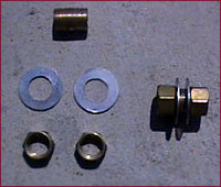 |
If it does not, check the bar for places where it catches. File any offending protrusions smooth. Otherwise, sand the inside of the sleeves until they rotate freely on the bar. Remove the sleeve and file or sand off 1/16" off each end. The sleeve is 1/8" too long and the compression nuts will not properly seat unless the excess is removed. Now take four 1/2 " washers and enlarge the holes until the sleeves will fit inside the washer holes. While you can buy 5/8" washers that will fit on the sleeve, they are too thick, have to be cut to clear the motor brace, require a longer brass sleeve, and stick out like a sore thumb. |
 |
Slide a brass compression nut and a washer on each side of the bar, and then put the bar back inside the holes in the vacuum motor brackets. The hook in the center of the center bar needs to be pointing upward and facing to the rear when installed. Put the brass sleeve, a second washer, and another compression nut on each end of the bar, center the bar between the brackets, and install the end nuts. Do not slide the bar into the connecting arms yet. |
|
Hold the center bar so that the brass sleeves are also centered in the holes in the vacuum motor bracket, and then tighten the end nuts. Always tighten by hand to ensure the tapered brass fittings do not cross thread. Rotate the center bar. It should rotate freely inside the brass sleeves. If it does not, the sleeves may be out of alignment or the interior of the sleeves may need to be sanded further. Adjust or sand as necessary. The bar has to rotate freely before continuing. Once the bar rotates freely, tighten the nuts with a 3/4" wrench and recheck the rotation of the bar, it should still rotate freely. Next, slide the bar to one side until you can put the center bar in the connecting arm. Slide it to the other side and install the other connecting arm, then re-center the bar. Install the spring supports and place both springs on their new mounting points. The doors should be held about halfway open, but may be a little lower than before. This is acceptable. Disconnect the springs, then slide the center arm about 1" to one side. Apply silicone lubricant to the area that will be inside the brass sleeves, then slide the center bar back into position. Remove any excess lubricant that could attract dirt and damage the fittings. Put the springs back on the new spring supports. The motor arm and the lever arm are the last items to be made. Their dimensions are critical. Even small errors will magnify into large problems if the measurements are off. Being short 1/8" on the motor arm will cause the doors to only open three-quarters of the way. If you are long by 1/8", the system will jam. If you are interested in seeing how the correct lengths were determined, see the Math sidebar below. |
|
MATH AND YOUR HEADLIGHT DOORS
First I tried to determine the correct lengths using a little basic math and some simple geometry. But determining these lengths mathematically requires taking into account the offset of the pivot arm (the hook) on the center arm and the fact that the centerline of the motor and the centerline of the center arm are neither parallel or square to each other or their endpoints. Compounding the problem is, while the center arm is rotating 90°, the motor arm is rotating 180°. While I had to take a lot of math back in college, I really did not want a refresher course in advanced geometry. But the geometry review was interesting and did help some, but in the end it was not anything complex that solved the problem. There’s a simple way to figure this out as long as you keep the pivot points lined up in the same plane. From the fully closed position, measure from the center of the hole in the center bar to the center of the motor shaft, with the motor in the middle of the adjustment slots. Do the same measurement from the fully open position. Subtract the fully closed position from the fully open position. Divide the result in half. The remaining value is the length of the motor arm from centerline to centerline. Subtract the motor arm length from the measurement in the fully closed position. This is the length of the lever arm from centerline to centerline. Note that the measurement from centerline to centerline is not the same as the end-to-end measurement because you have to account for the thickness of the material. Disconnect the springs while doing this or they will affect the measurements. Because both the motor arm and lever arm rotate, any errors in length will be doubled. For example, if the motor arm is 1/8" short, the lever arm will travel downward 1/4" less. While this does not seem like much, consider that this 1/4" translates to almost 1" of reduced travel in the headlight door. If the motor arm is too long, the doors will fully open one time, but will not do anything else because the motor is jammed. This is true for errors in the lever arm length as well. Without getting into all the principles of fulcrums and levers, just realize that small errors translate into big ones at the doors, so when you make your lever and motor arms, they need to be Exactly the correct length. |
|
DECISION TIME There are two ways to make the motor arm. The first is to graft some additional metal on to the original one and the second is to fabricate a new arm. The first is much easier, but there is one compelling reason to build it from scratch, which I’ll cover when I get to that arm. Diagram 9 illustrates both motor arm options. All of the options require cutting thin grooves in the 5/16" steel rod so I’ll start with that. Put the vice grips on the end of the 5/16" bar about 1/4" from the end. (Or, put the rod in a vice, either works) Put a washer on the rod so the saw will not catch on the vice. Take the hacksaw and slowly cut a groove around the bar while keeping the saw blade flat against the vice grips. Keep the depth of the groove uniform. When the blade’s teeth are almost completely obscured, start checking with an E-clip every other rotation. When the E-clip will snap in place and holds securely, the groove is done. Lever arm options one and two need two grooved rods each about 1" long. For lever arm option three the grooves are cut into the lever arm once the bends are made. (Thanks to Joe Garbacik who reminded me about this method.) Or you can drill a hole in the rod and use cotter pins instead. Either method works. |
| LEVER ARM: OPTION ONE Start making the arms by taking a 3/16" x 3/4" x 8" bar of metal and drill a 5/16" hole about 3/8" from the end. One-eighth inch stock will not work as material this thin and narrow tends to bend at this length. Some 1/8" stock holds up fine but all the readily available stuff at this width and length bends under pressure so I cannot recommend 1/8" stock for this option. Measure 7-1/4" down from the center of the first hole and drill a second one, also 5/16." Take one of the 1" grooved steel rods, put an E-clip on it, slide a 5/16" washer on it, put the center bar on next, followed by the 8" bar. Make sure everything is snug, move the rod back out 1/16" for expansion, then tack weld the 5/16" rod to the 8" bar. Remove the E-clip, 5/16" washer and center bar, cut off the excess rod beyond the two tack welds, then finish welding the rod to the bar. Round off the ends of the bar. LEVER ARM: OPTION TWO Take two 1/8" x 3/4" x 1-3/4" bars of metal and drill a 5/16" hole about 3/8" from the end of both. Round off the ends of both bars on the drilled ends. Cut a 5/16" wide slot 3/4" deep in the end opposite the holes in the center of both bars. Take a 6" section of 5/16" bar and center it in one of the slots. Weld it in place. Place the slot in the second 1-3/4" bar on the other end. Make sure the two bars are perfectly level, the rod is centered in the bar, and the center of the 5/16" holes are 7-1/4" apart, then weld the second bar to the rod. Then take one of the 1" grooved steel rods, put a E-clip on it, slide a 5/16" washer on it, put the center bar on next, followed by one end of the lever arm. Make sure everything is snug, move the rod back out 1/16" for expansion, then tack weld the 5/16" rod to the lever arm. Remove the E-clip, 5/16" washer and center bar, cut off the excess rod beyond the two tack welds, then finish welding the rod to the bar. The inside welds on the center bar side of the lever arm have to be ground smooth to a point about 3/4" down from the grooved rod for the lever arm to clear the hook on the center bar. Make sure the welds on the opposite side are sound as they will support the majority of the load. LEVER ARM: OPTION THREE This is definitely the hardest piece to make. Start making the arm by taking a 5/16" steel rod and putting about 1" into a vice. Heat the rod with a propane torch just above the teeth of the vice for five to ten minutes. While continuing to heat the rod, bend the rod over into a 90-degree bend. Hammer on the rod just above the vice jaws or the rod will curve. Continue to hammer on the rod until there is a sharp 90-degree bend at the jaws of the vice. Remove the bar and let it cool. Straighten any curves in the rod beyond the bend. Measure from the inside of the 90 degree bend to a point 6-15/16" down and scribe the bar, then put the rod in the vice so that the first bend is below the vice and the 6-15/16" mark is right at the edge of the vice jaws. Heat, hammer and bend the rod the same way as before. Pull the rod over the original bend so the ends of the rod end up pointing in the same direction. The centers of the bent sections should end up at 7-1/4" apart. Take a file and clean up around the 90-degree bends where the vice and hammer scarred the rod. Next slide a washer, a 1/8" bar with a 5/16" hole in it and a second 5/16" washers on the bar. Mark the bar where the second washer ends. Remove the bar and washers, then cut the rod at 1/4" beyond the mark. Cut a groove using the technique described earlier on the mark at 1/16" beyond the mark. Repeat for the other side of the bar. Reinstall the washers and 1/8" bar on each end. Use the bar to keep the washers perpendicular to the bar and to hold them in place while you weld the washers to the bar. One spot weld on each side is sufficient. One alternative to this method is to build two ends and weld them together so that they are 7-1/4" apart. You can then grind down the weld so that it is not visible. But unless you are extremely competent with a welder this setup will soon break at the weld. |
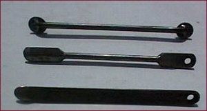 |
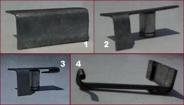
The three lever arms, starting at the top with Option Three. Option Two is center, Option One is the bottom. |
| MOTOR ARM: OPTION ONE The easiest way to make the motor arm is by adding some metal to the original arm. First cut off the end of the original lever arm at the bend that is most distant from the motor shaft hole (the tapered one) Make the cut with the saw held parallel to the long edge of the arm. Cut a 1" piece of metal to match the width of the original arm. Cover the tapered hole so welding splatter cannot damage the grooves, and then weld the new piece to the arm. Measure 1-3/8" from the center of the tapered hole. Make sure you measure parallel to the flat sections and not diagonally across the piece or the hole will be in the wrong place. A framing square is best but a tape measure on its side will also work. Mark the second point. Center punch the mark with an awl to ensure the drill bit does not drift when drilling the hole. Drill a 5/16" hole at that point. Take the second 1" grooved rod, put the E-clip on it, then a 5/16" washer followed by the lever arm and the motor arm. Make sure that the larger side of the tapered hole is facing away from the E-clip. Cover the tapered hole again, and then tack weld the rod to the arm. Remove the E-clip and other pieces, cut off the excess beyond the tack welds, then weld the rod in place. If you are using lever arm option three, do not install a grooved rod. MOTOR ARM: OPTION TWO Take a 1/8" x 3/4" x 3" piece of stock and drill a 5/16" Hole in one end. Center the motor bolt and lock nut over the hole. Mark a point about 1/8" beyond the lock washer. This is where the first bend will go. |
 |
Put the stock in the vice and bend it 45 degrees. Measure perpendicular to the flat part up 7/16", then shift the tape measure over until it touches the bent part. This is the second bend line. Put the stock in the vice at the bend line. Use another piece of stock and a hammer to bend the piece 45 degrees. Using a hammer alone will bend the first flat area. Put the piece down on a flat surface with the hole facing down. |
|
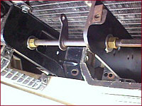
Put something under the piece so it will lie flat. Measure 1-3/8" from the center of the first hole and mark the center of the second hole. Center punch the spot with the awl to make sure the drill bit does not drift, then drill the second hole. Weld a 1" grooved rod in place using the same techniques described earlier. If you are using lever arm option three do not use install a grooved rod. A reamer, a die grinder with a conical burr, or a Dremel tool with a conical burr works best to taper the hole but a sharp knife and a lot of patience will work also. After doing it once with a high quality steel scissors blade, I recommend spending the money for at least a reamer. Figure on 2-4 hours additional time to do it with a knife. The angle of the taper must match the taper angle of the original motor armhole. Test fit often, as the tapered hole must be flush against the motor shaft or it will slip. Don’t worry about the grooves that the original motor arm has, they will develop over time. This option is harder to make than the first one. Its redeeming feature is that the angles of the bends can be changed to shorten or lengthen the spacing between the holes while the weld on the original motor arm will not allow changes in the bend angles. INSTALLATION That completes the metal work, so it is time to install the parts. Attach the motor to the bracket midway along the slots using the 1/4" hardware. The correct sequence is 1/4" washer, bracket, motor, 1/4" washer, 1/4" lock washer, and 1/4" nut. Finger tighten the nuts, as the location of the motor will have be adjusted soon. Just tighten them enough to hold the motor in place. Slide the bracket into the car and bolt the bracket in place. The center section of the bracket should line up with the edge of the vacuum motor brace or slightly beyond it, not under it. Install and tighten the two 1/2" top bolts before the bottom bolt to ensure the electric motor bracket will square up the vacuum motor brackets. Connect the lever arm to the motor arm using one 5/16" washer and one E-clip. Connect the lever arm to the center arm using another 5/16" washer and E-clip. The grooved rods should point toward the driver’s side. (Passenger side for lever arm option three.) |
|
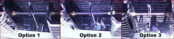
Place the motor arm onto the motor shaft and put the lock washer and nut on the shaft also. Raise or lower the motor until the lever arm and motor arm are in a perfectly straight line, then tighten the motor shaft nut. The motor arm will be below the lever arm, pointing upward and angled slightly to the rear when properly positioned. Rotate the white knob at the bottom of the motor 3/4" of a turn clockwise. While pulling the motor upward, tighten the three 1/4" motor retaining bolts. Rotate the white knob at the bottom of the motor clockwise to cycle the motor through one complete opening cycle. This will take a while. When the motor arm and lever arm are again in a straight line with the motor arm now behind the lever arm instead of below, it has finished the opening cycle. Check to make sure the doors are completely open. At a minimum they must be within 1/2" of the stops. If not, or if the doors hit before the cycle completed, the arms have to be changed. This is where being able to change the angles and thus the length of the motor arm (option two) becomes such a handy feature. Pull the motor arm, give it a couple of blows with a hammer and the motor arm is longer or shorter as needed. While it will not fix major errors, it can fix minor ones and is much easier than making new arms. Put the arms back in place and see if the door now opens properly. Cycle the motor back down to the closed position and make sure the doors still close completely. If they did not, adjust the position of the motor until they do, then retest the opening cycle. Leave the doors in the open position for the electrical phase. If both arms are the right lengths and the doors still will not open fully, look at the math section and go through the calculations to determine the custom arm lengths required for your car. STAGE 4: WIRING There are two decisions to make with the wiring. The first is where to put the relay and the second is where to pull the power. Put the relay in the engine compartment and you do not have to run as many wires into the passenger compartment. You will have to insulate the relay against the weather and figure out where to mount it. Putting the relay in the passenger compartment will protect it from the weather and solve the mounting location but you have to run more wire. If you put the relay in the engine compartment you also have to decide where you will get power from, directly from the battery or from the fuse panel. Both options work equally well, it is simply a matter of looks. Decide which is best for you. Diagram 10 illustrates wiring with the relay mounted in the passenger compartment. Diagram 11 illustrates wiring with the relay in the engine compartment and power supplied by the fuse panel. Diagram 12 illustrates wiring with the relay in the engine compartment with power from the battery. The motor does not draw any power when the doors are open or closed, only when the doors are opening or closing. If you examine the wiring diagrams it seems as if the motor has a constant 12V being applied, but due to the design of the motor it does not draw any power when stopped. While it is a neat feat of engineering, what’s important to you is that the only power drain when the doors are open is from the relay and the relay does not require that much. The original Ford Probe wiring system has what appears to be 20 or 22 gage wiring, but due to the longer lengths of wire required here use a minimum of 18 gage wire. The wire I used was 25’ of 18 gage four-strand wire sold as a trailer harness. The system does not need that much wire; three runs of 15’ and one run of 3’ is sufficient to handle all wiring possibilities. The choice of wire colors does not matter either, but being consistent with color codes whenever possible will make installation and troubleshooting much easier. The connections between wires have the potential to be a problem if not properly insulated. All of the joints need to be soldered, then sealed against the elements or corrosion will set in. Use shrink tubing and a sealant like liquid electrical tape at every wire joint. Use dielectric grease in the motor connector to seal water out of it. Use dielectric grease at the relay connector if it is inside the engine compartment for the same reason. If the relay is in the engine compartment, each wire opening in the connector must be filled with sealant once the wires are plugged into the connector. Let the sealant dry before applying dielectric grease to the connector. While the pieces of the circuit can be in different places, they all run wires from the same places to the same terminals. As always, when working with electrical circuits, disconnect the battery first. Starting at the motor connector, connect the black wire to ground using one of the ring connectors. The black wire with a white stripe is run to the inline fuse holder, then to a constant power source. Leave the fuse out so the motor does not activate while making the connections. The black wire with a red stripe (down) is run to relay terminal #5, which does have power when the relay is off. The black wire with a blue stripe (up) is run to relay terminal #4, which does not have power when the relay is off. Besides the two wires already mentioned, the relay has three additional wires going to it. One is the input power source being switched between terminals #4 and #5. Connect this terminal, #3, to the power wire going to the electric motor between the motor and the inline fuse holder. Connect relay terminal #2 to ground using the second ring connector. The last wire, from relay terminal #1, goes to the red wire with a yellow stripe that runs between the headlight switch and the dimmer switch. Install the two blade terminals at the other end of the wire, about 2" apart. Make sure to use the terminal with the retaining tab so it will stay inside the connector. Next, remove the red wire with a yellow stripe from either the dimmer switch connector or the headlight switch connector. Either will work, but the dimmer switch connector is much easier to get to and work with. Using a paperclip or fine screwdriver, push the tab on the side of the metal terminal in and release the terminal from the connector. Plug the new female terminal into the connector. Slide a section of shrink tubing over the wire, and then plug the remaining new terminal into the old terminal. Cover the connection with shrink tubing and electrical tape. The table below summarizes the wiring layout. |
| ORIGINAL | CONNECTING WIRE | RELAY TERMINAL | CONNECTING WIRE | MOTOR CONNECTOR | MOTOR |
| RED wire w/YELLOW stripe | BROWN | #1 | ----- | ----- | ----- |
| Ground | BLACK | #2 | ----- | BLACK w/BROWN hash marks | BLACK |
| POWER – Fuse Panel | Inline fuse holder – WHITE | #3 | WHITE | BLACK w/WHITE stripe and BROWN hash marks | WHITE |
| ----- | ----- | #4 | BLUE | BLACK w/BLUE stripe and BROWN hash marks | YELLOW |
| ----- | ----- | #5 | RED | BLACK w/RED stripe and BROWN hash marks | RED |
|
Before making the first connection, decide the relay position and the power source location. Next, lay the wires in place to determine the correct length for each wire. There will be one to three wires running from the passenger compartment to the motor. Route those wires through the firewall hole where the vacuum hoses entered the car. Cut off any excess, but leave some slack in the wire for routing or future repairs. Solder the four wires going to the motor to the motor connector wires. If the relay is in the engine compartment, solder the wires going to the relay also. Apply shrink tubing and sealant to each joint. The same applies for the power wire. Take the body plug and put a small hole in its center. Run all the wires going into the passenger compartment through the hole in the body plug and apply sealant around the hole, then solder and seal the connections on the ends of those wires. Connect all wires with the exception of the power wire and the wire to the dimmer switch. Now bring all the wires going through the firewall to the front of the car. If the relay is in the passenger compartment and you soldered the wires to its connector through the hole in the firewall, unplug the motor connector and pull the harness out of the car that way as the relay connector will not fit through the hole in the firewall. Reconnect the motor connector. Connect the power wire to the positive side of the battery if it is not already there. Temporarily cover the female blade terminal on the dimmer switch wire with tape so it will not short out while testing the system. STAGE 5: TESTING AND FINAL INSTALLATION Clear the area around the headlight doors and make sure the wiring is not in the way, then put the 20A fuse into the fuse holder. The headlight doors should close when the connection is made. Operate the doors several times by touching the dimmer switch blade terminal to power. When it is connected to power the doors will open, when it is disconnected the doors will close. Check to see if the doors are opening fully. Watch the doors and the lever arms. If the doors jam partially open or the motor arm does not travel 180 degrees each time, immediately disconnect power and correct the problem. See the troubleshooting chart for more information. Otherwise, listen and look for spots where the doors hit the housing hard. These areas are candidates for padding. A coating of PlastiDip or gasket compound on the doorstops can soften the impact of the closing. If the doors hit at the top, check the rubber pads to see if they are worn or missing. A small piece of split rubber hose can be put on the top of the housing if the noise is coming from the outer edge of the door is hitting the housing. When the doors are operating properly, install the new wiring harness beside the original. Connect the dimmer switch wire as described above. Connect the power wire to the fuse tap if the power source is the fuse panel, otherwise leave connected to the battery. Use the fuse adapter to get power from one of the fuses. Make sure it is put on the power side of the original fuse. I recommend using either the cigarette lighter or the A/C since they have the largest power feed. These fuse adapters are hard to find for the old style fuses but the new blade style fuse adapters can be bent to work also. Once the wires are in place, a wiring loom can be placed over the original harness and the new wires to keep the wires from sagging and to improve the appearance. If a loom is not used, tape the wires to the original harness every 6-8 inches. Put the wires under the original harness and close to the fender apron so they will not be easily noticeable. You could also wrap the wires to the harness using non-sticky vinyl tape like the material covering the original harness, which would also give the harness a like new appearance. If it is not available locally, The Eastwood Company sells the stuff. Put the new wires back inside the wiring clips and close the clips. Reconnect the battery. If you can find the pins used in the firewall harness connector block you can run the wires through that for a truly original look. Since the original harness does not have any spare pins in it you will have to get these pins from a junkyard. This would eliminate the wires running through the body plug but the amount of work may not justify the end result. Remove the motor arm shaft nut and lock washer, and then remove the motor bracket and motor. Do not remove the motor from the bracket or you will have to readjust the motor. Install the water boot on the bottom of the motor. This boot keeps water from rusting out the steel shaft on the safety wheel and keeps magnetic particles from sticking to the motor housing. Reinstall the motor bracket and motor. Re-connect the motor arm to the motor shaft. Tighten the 14mm nut. Reinstall the center grille and the license plate holder. This completes the installation. Check the lever arm about every three months to make sure it is not shifting to one side and lube under the brass bushings once every six months. TROUBLESHOOTING CHART |
|
SYMPTOM |
POSSIBLE PROBLEMS |
RECOMMENDED SOLUTIONS |
| Doors do not open after tightening brass compression nuts | Nuts on brass bushings are binding or center bar not aligned between outer arms | Check vacuum motor brackets for proper alignment.
Re-align center bar. Check the compression nuts to make sure they are not cross-threaded. Sand the inside of the brass sleeves for additional clearance. |
| Motor/Lever arms do not line up with center bar | Center bar out of alignment | Slide center bar to one side until lever arm lines up with center bar. |
| Doors open once, but will not operate again | Motor arm and/or lever arm are too long | Confirm lengths of both arms. Adjust lengths as necessary. Manually cycle though one complete revolution of the motor to ensure the motor is not binding with new arms. |
| Blown fuse | Replace fuse. Manually cycle though one complete revolution of the motor to ensure an incorrect arm length did not cause the motor to bind and blow the fuse. | |
| Motor arm is jammed on a bolt head | Grind down the bolt head and or tip of lever arm rod until there is at least 1/16" clearance, with 1/8" the recommended clearance | |
| Doors do not fully open | Motor and/or lever arms are too short | Confirm lengths of arms. Check distances if arms are correct and build arms to measured lengths instead. |
| Doors do not open or close | No power | Check the relay power input (terminal #3) for power. Check fuse if no power is present.
Apply power to terminal #1 and listen for click. If the relay does not click, check the ground wires |
| Motor is unplugged | Plug motor into circuit and retest. | |
| Motor arm is jammed on a bolt head. | Grind down the bolt head and or tip of lever arm rod until there is at least 1/16" clearance, with 1/8" the recommended clearance | |
| Relay makes a loud clicking noise but doors do not open. | No power at main feed | Check relay terminal #3 for power. Check fuse if no power is present. |
| Poor connection | Tighten connections on relay terminals #3 and #4. | |
| Unusually hard or noisy contact between door and grill assembly | Rubber pads are missing on grill assembly | Install new rubber stops in grill assembly. |
| Motor and/or lever arm is slightly too long | Change arm lengths and readjust motor position to compensate. | |
| Grill assembly is slightly misaligned and outer edge of door is hitting grill assembly | Add a plastic coating (PlastiDip or gasket sealant) or a length of split host to top edge of grill assembly. | |
| Unusually hard or noisy contact between door and door stops | Motor is too low in bracket | Raise motor slightly in bracket.
Add a plastic coating (PlastiDip or gasket sealant) to top of doorstops if problem persists. |
| Motor sounds significantly different between opening and closing cycles | Doors are not properly balanced | Check springs to ensure they are on the new spring supports.
Remove the center bar and confirm balance of each door. |
| Doors swing past their stop point and stay partially open or closed | Motor arm is improperly installed. | With the system in the off position, realign the motor arm to be in a straight line with the lever arm. |
| Doors open when lights are off and close when lights are on | Wires between motor and relay are reversed | Connect wires according to wiring diagram. |
| Motor arm installed 180 degrees out of phase | Remove motor arm and reinstall it pointing in the opposite direction. | |
| Doors rattle when driving | Motor out of alignment | Reinstall motor following installation procedures. If problem persists, reinstall using a full turn instead of 3/4" turn. Coating the doorstops with a rubber or plastic coating will also reduce noise. |
| Worn rag joints | Repair or replace coupling arms | |
| Center bar keeps sliding to one side | Front grill out of alignment | Align grill and vacuum motor brackets. |
| Worn Brass bushings | Replace brass sleeves with new ones.
Drill one hole beside each inner brass compression nut and install the original retaining pins in the new holes. |
|
POST PRODUCTION NOTES
Initial Feedback I had the system in my car for a little over three months before I pulled it out for this article. Everything has held up extremely well. The one failure I found was the lube I used in the brass sleeve was completely gone. For that reason I recommend using a silicone-based lube instead of light grease. The bearing will survive without out lube for several years as it is not under any heavy pressure or dealing with high RPM's, but it will last even longer with lube. Lube it whenever you lube the chassis and it should be fine. If the center bar was sanded or filed to bare metal it will develop a heavier rust pattern the second time around. Paint the bar with a thin coat of paint to protect the metal. Lube is required in the sleeve if the bar is painted, as the sleeve will remove the paint. The relay makes a loud click when activated. This is not an issue if the relay is in the engine bay, but it might be if the relay is in the passenger compartment. The engine noise and the noise of the doors opening might hide the click of the relay and it might not. I designed the system with the relay in the passenger compartment, but the test vehicle had it in the engine bay so I did not get to check the noise issue. Metal Thickness vs Availability As stated earlier, I wanted to make this out of readily available materials. Because of this the motor bracket is made of 1/8" stock. One-eighth-inch stock is overkill. It is way stronger than needed. Even worse, in an accident it might puncture the radiator where a thinner metal would fold up. While 16 gage is too thin, 14 or 12 gage stock would be the better solution if it were available. If 14 or 12 gage metal is available in sheets, look at using it instead of the 1/8" material. It does not have to be new metal, either. The first workable bracket I built was made from a flattened out lower control arm. Five-Sixteenths-Inch Washers Not all washers are made equal. Washers of the same size can have different thicknesses, different internal diameters, and different outer diameters. Under most circumstances these minor variations aren’t an issue. For the washers that are going on the 5/16" rods, the internal diameter is an issue as these washers help keep the arms centered in the car. If the internal diameter is too large the washer could also catch on the E-clip and knock it off the bar. Check the internal diameter of the 5/16" washers closely, it needs to be 5/16" not 3/8" as some are. If the 5/16" washers are too large, look at the 1/4 " washers. Some 1/4" washers have a 5/16" internal diameter. Splash Shield The system really could use a splash shield to protect the motor from direct impacts from road debris. One possible solution is the windshield wiper motor plastic housing used on most early ‘70s Fords and Mercurys. The two motors are about the same size. The only problem is cost. Buying a second windshield wiper motor just to get the housing is not cost effective. But if you have one gathering dust it can be cut to work. Simply use longer bolts on the front two motor mount bolts and put a second nut on to hold the housing on. A front license plate will also protect most of the motor. Center Arms & Pins The center arm has two pins to keep the arm from sliding to one side. For most cars these pins are unnecessary because the center arm does not move. But for those cars that did need them it might still be an issue when the system is converted. If the center arm slides to one side it can cause the lever and motor arms to bind or jam. The tolerances are deliberately close on these parts to reduce the ability for the center arm to move, but age and wear will eventually catch up. There are two possible solutions for this. The first is to find some thinner nuts to use instead of the brass compression nuts. I used stainless steel washers and brass nuts on purpose so any metal interactions would be minimized, but replacing the sleeve every few years is much cheaper than replacing a burnt out motor. If you can find a thinner nut, use it. The other solution is to drill new holes in the center bar. While this violates the principle of not modifying an original part it may be required if the center bar tends to drift on your car and smaller nuts are not available. Fortunately they are still available and center arms do not wear out often. Painting Brass I did not paint the brass parts because I was not sure of the proper procedures to make paint adhere to the brass. They really should be painted or they will deteriorate in a few years, especially in those states where road salt or ocean breezes are a normal occurrence. Be careful not to scratch the paint when installing them or paint them after they are installed. Emergency Procedures If the system fails the headlight doors will have to be opened manually to drive the car at night. That’s the reason for the white wheel at the bottom of the motor. Turning that wheel will rotate the motor and lift the doors. Unfortunately it is really hard to get to that wheel where it is located. Besides, there is an easier way to get the doors open. Disconnect the lever arm from the center arm and put the springs back in their original positions and the doors will be held open. Tie the lever arm down or remove it completely so it does not bounce around and put a hole in the radiator. What did I miss? A lot, probably. Hopefully, nothing important. I tried to strike a balance between level of detail and simplicity--how much detail to go into about welding, metal fabrication, tool safety, metal interactions, the reason why something was done one way instead of the other, the list goes on and on. At this point I’ve put more time into writing this than it took me to design and build the system. Hopefully I gave enough information so the concept came across and the missing details could be extrapolated from there without getting lost in the weeds. If not, there’s always email. Copyright The design for this project is mine and it is not for sale. You are free to use the design to make one for yourself or to help a friend make one, but you cannot manufacture them for sale or sell the plans. To borrow a term from the software industry, this design is now "Freeware." The plans or the final product cannot be sold for profit. If I wanted someone to make a profit from this I would have taken the advice of several friends and patented the idea or produced a kit. Instead I’ve decided to give it away to those Cougar owners who need it or could benefit from it. My design, my choice. Photos and images by Bruce Habel |
Quelle: http://www.theclassiccougarnetwork.com/tccn2/tech/restomod/restom10/restom10.html